Note: This is a prototype of an FFMP, a Free Flying Micro Platform.
Normally, I am restricted through the position of my eyes in about what I actually see. If I would have an additional third eye that is not physically connected to my body, I would have the possibility to look at myself from above or from a perspective in front of me.
First I tried to determine the most appropriate design.
 |
Four ducted fans wrapped in donuts. This idea is obviously UFO inspired. Two of the four electric impellers will run clock-wise, two of them counter-clockwise. Like that, the helicopter can be controlled by a combination of speed changes of the four rotors. (The Keyence Gyrosaucer and Engager, as well as the Roswell Flyer use the same technique. And here is the Engager manual, for more details.) The donuts can be filled with helium to produce additional lift. Additionally, they act as bumpers or airbags if the helicopter bumps into something. The batteries and the rest of the electronics are placed in the sphere in the middle. (Ken Perlin gave me the tip to tilt the donuts slightly to the center. Like that the vessel will gain stability.) |
 |
Four Ducted Fans in an inflated basketball. Another idea was to put the four ducted fans in a sphere. The ball would hide all internal "organs," just hovering "magically." Of course the sphere does not have to be massive: filled with a gas lighter than air increases the lift remarkably. However, there are two problems: first, a sphere takes a lot of space--it makes the helicopter look big, and that's not what I want. Second, the center of gravity is in the middle, close to the propulsion units. Because of that, the helicopter would tip over very easily. To prevent that, the control system needs to have a very short "reaction time." |
 |
Four Ducted Fans in bedroom lamp. The idea behind this design is that the lower the center of gravity, the slower the helicopter will get out of balance. It still won't be stable like that, but roll and pitch changes will not occur as sudden as with a flat vessel like the donuts or the sphere. The purple, transparent hull protects the fans and prevents people from touching the rotors. The batteries and the electronics sit on the bottom of the foot of the "lamp." |
 |
Four Ducted Fans attached to a tetrahedron. If four impellers are mounted with two degrees of freedom (pan and tilt) in the corners of a regular tetrahedron, the vessel would be very universal and agile--and on the other hand, very unstable. The advantage of such a configuration is that the vessel can roll 360 degrees (there is no top or bottom), and do other unconventional flight maneuvers. Unfortunately, the spiky ends of the ducted fans as well as the air intake openings are not protected. Additionally, rotating the ducted fans and tilting them needs probably very powerful servos. (Thanks to Dan Overholt for the brainstorming.) |
 |
One ducted fan on a stick. After I have heard how loud electric ducted fans are, I thought about concepts with as few as possible noisy engines. I have tested one small ducted fan. I was holding it vertically, and surprisingly, the tendency to yaw--the torque reaction--was not very significant, once the fan has started up. This is probably because the mass of the rotors is relatively small compared to normal helicopter rotors. So I came up with the idea that four small ailerons could compensate for the yaw tendency. The same ailerons could be used to deflect the airflow to move the vessel backward, forward, and sideward. If the mixing of the yaw, roll, and pitch function is made by the control system, four servos are necessary, one per aileron. (However, if there are separate ailerons for the yaw compensation, only three servos would be necessary--but more ailerons.) The battery cells are placed at the very bottom of the tube to keep the center of gravity as low as possible. And again, the donut is filled with air or helium to provide additional lift and to protect the impeller. |
There are more pictures of the design studies.
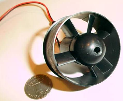
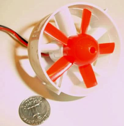
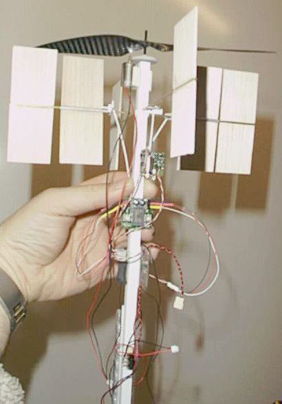
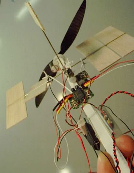
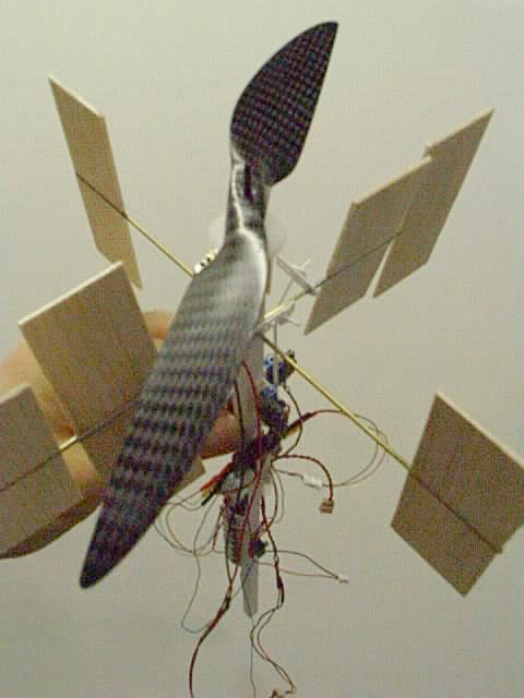
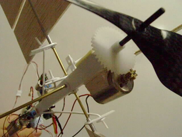
I decided to build the first prototype of a Zero G Eye in the style of the "One ducted fan on a stick." However, the ducted fans were not efficient enough. Only a special propeller-gear-motor-combination had a sufficient thrust-to-weight ratio:
| . |
 |
 |
 |
| Fan/Propeller | Cox/Estes | Sonic Blast | WES Carbon Fiber 20cm gear 1:6.7 |
| Diameter | 50 mm | 60 mm | 200 mm |
| Rotor weight | 1 gram | 2 grams | 2.3 grams |
| Tube weight | 7 grams | 11 grams | - |
| Tail cone weight | 2 grams | 1 gram | - |
| Motor weight | 24 grams | 24 grams | 12.2 grams |
| Total weight | 36 grams | 39 grams | 14.5 grams |
| Max thrust @ 9V | 44 grams | 51 grams | 91 grams |
| Max lift/weight ratio | 1.27 | 1.28 | 6.27 |
| Max net payload | 10 grams | 11 grams | 76.5 grams |
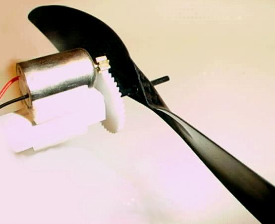
It was clear that the available ducted fans can't have the same efficiency as the bigger propeller. Therefore, my prototype would not but a "ducted fan on a stick," but rather a "geared propeller on a stick." However, a carbon fiber ring around the propeller (future improvement) could make the propeller less open and dangerous.
| Component | Weight | Model and manufacturer | Origin
| Receiver | 2.1 grams | SHR-RX72 by Sky Hooks and Rigging | Canada
| Servos | 3x 2.4 grams | LS-2.4 by WES Modelltechnik | Germany
| Gyro | 4.8 grams | PG-03 by Grand Wing Servo-Tech | Taiwan
| Electronic speed controller | 0.9 grams | JMP-HF9 by Jean-Marie Piednoir | France
| Motor and gear | 12.2 grams | Micro DC 5-2.4 with gear 1:6.7 by WES Modelltechnik | Germany
| Propeller | 2.3 grams | Carbon Fiber 20/10cm, by WES Modelltechnik | Germany
| NiCd battery | 31.5 grams | 50mAh Cadnica cells by Sanyo | Japan
| Ultrasonic beeper | 6.0 grams | FreeD by Pegasus Technologies LTD | Israel
| Fuselage, flaps, hinges, pushrods, clevises | 15.0 grams | hand made by Stefan Marti... | USA/Switzerland
| |
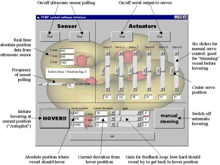
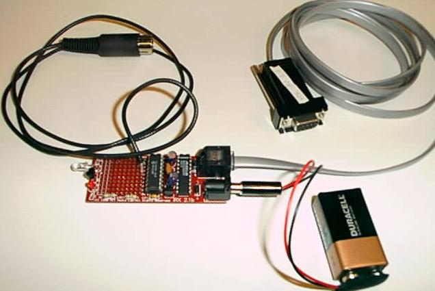
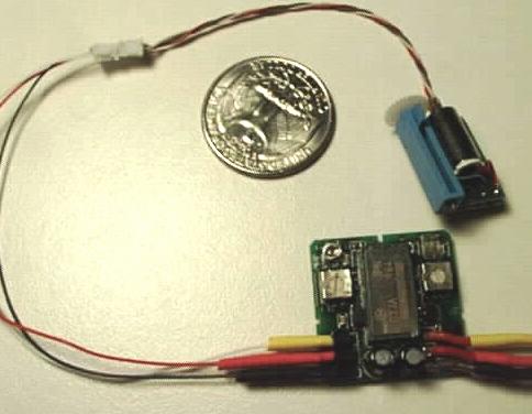
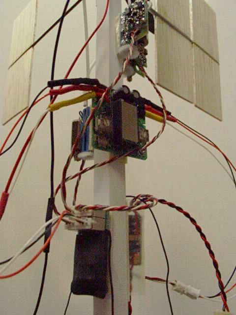
| The laptop outputs serial data. However, the R/C transmitter accepts only a special sequence of pulse width modulations. The IRX board (hardware designed by Rob Poor) is programmed so that it takes serial data from the handset and generates this PWM. The code for the PIC on the IRX board is quite simple, but it turned out to be almost impossible to generate a clean signal: The PIC has to listen for incoming serial data, but at the same time, the PWM signal has to be repeated continuously. However, the transmitter/receiver do not appear to have problems with it. Here is the PIC code. (Thanks a lot to Dan Overholt for helping with the PIC code programming.) |
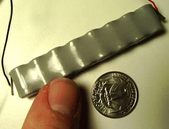
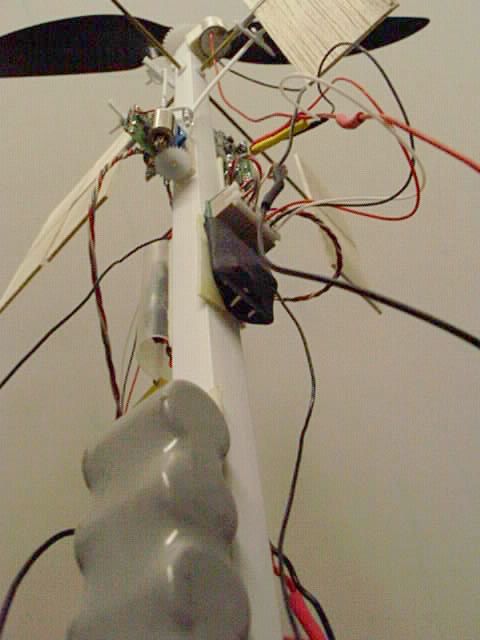
| I use 8 cells 50mAh (9.6V). The pack weighs 31.5 grams and can give me more than 1000 mA. Nickel Cadmium is a well-known battery type, but also very old. I have looked into many more recent ones, e.g., Nickel Metal Hydride (NiMH), Lithium (primary cells), Lithium Ion (rechargeable), Manganese Dioxide (ZnMnO2), Lithium Manganese Dioxide (LiMnO2), Silver Oxide (ZnAg2O). Not ONE of them could deliver the current that was required (more than 1A), given a maximum weight of 31 grams at 9 volts! It seems that there is still no alternative to NiCds if it comes to extremely high currents (20C!!) at relatively high energy density. However, it has to be said that the approximately 30% of the energy of the 50 mAh NiCd is lost in heat when used so far above its limits, so it is actually a 35 mAh. To increase flight time, primary batteries could be used, e.g., three Duracell CR2 750mAh primary lithium cells. Together, they are 33.3 grams, which is only 1.8 gram more than the NiCds. At a 1A load, they give probably only 425 mAh, which is more than ten times better than the NiCds. The only downside is the price: each 20-minute flight will cost $15. |
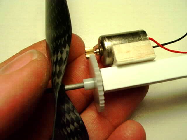
| The Micro DC 5-2.4 is combined with a gear of 1:6.7 ratio, a double ball-beared carbon output drive shaft with diameter 2 mm, and a molded carbon fiber propeller. The manufacturer says that at 9 volts, this propulsion set takes 1.06 A current, produces 9.5 Watts, spins the propeller with 4210 rpm, and delivers 91 grams of thrust; the gear efficiency is supposed to be 93%, which is remarkably high. The motor itself has a maximum efficiency of 75.3% at its rated 5V, but probably much lower in this propulsion configuration. Due to the fact that the DC 5-24 is built to produce 2.45W at rated 5V, it will live only 5-15 hours when driven with 9.6V. After that, the brushes will have to be replaced. (Thanks a lot to Kai Huber for correcting me with the gear/motor efficiency. He has an incredibly interesting German page about electro motors, gears, and propellers for slow flyers.) |

| The WES servos are the lightest (2.4 grams) commercially available servos. Although servos like the Futaba Hitec HS-50 are only 30% bigger in size, they weigh twice as much (5 grams). The question was only if the output torque of 175 grams would be enough, but during the tests I did, it seemed to be enough to drive the flaps and rudders. However, it has still to be determined if the occasional stalling of the servos is due to too low voltage, too high force, or a messed up pulse width modulation signal from the IRX board. |

| The receiver is the lightest available with truly proportional four channels. If the weight of the receiver has to be reduced even more, the plugs can be removed and the servos could be soldered directly to the board. Alternatively, products like Z TRON's infrared transmitter/receiver would weigh even less, but probably require line of sight. |

| The speed controller weighs less than one gram and is a very advanced piece of equipment (RISC processor, Auto-Calibration, Safe-Start): it provides a very smooth output voltage due to a clock-frequency of 60kHz. Additionally, it powers the receiver, so that no special receiver battery is necessary. |
| Without its plastic case, the PG-03 is definitively the lightest gyro with electronics (5 grams). Note that the heading angle of the vessel is NOT controlled by the laptop: the computer has no information about the heading angle. Therefore, the gyro controls the yaw servo on its own. However, since it is NOT a headlock gyro, eventually, due to added up position errors, the vessel will lose its original heading angle. A deviation of more than 30 degrees from the initial position would make the helicopter crash inevitably, since the X and Y axes would be confused by the control program. (Solutions to solve this problem are on the way.) |
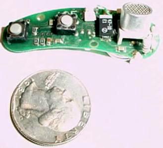
| The main idea behind this vessel is that absolute position is enough to stabilize a small helicopter. So the only sensor is this ultrasonic beeper. It is taken from the ring of a FreeD mouse, a wireless joystick. The ultrasonic sensor is from a 3DZ, a similar product based on the same technology. The beeper sends some kind of ultrasonic chirps and is synchronized with the sensor sitting on the floor via infrared. Line of sight between the beeper and the sensor on the floor is absolutely necessary, especially for the infrared link. |
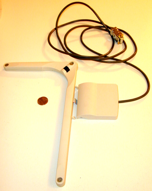
| The sensor is an "L"-shaped piece of plastic, with three ultrasonic transducers on the corners, as well as an IR sensor in the middle. It is connected via serial port to the laptop. |

| The radio handset takes the PWM signal from the IRX board and transmits it to the receiver on the vessel. Almost any kind of brand and model could be used for this purpose; it just has to have a trainer cord plug. I have used a Futaba 6XA, a standard 6 channel model. Having real joysticks "in the loop" makes it also easier to conduct pre-flight checks, testing the transmission and the servos. To switch to the trainer cord input and let the computer control the servos, the user has to keep pressing a button on the upper left side of the handset. As soon as s/he releases this button, the handset (and hopefully a qualified pilot on the joysticks...) takes over the control over the vessel. |
| 
| 
|
| 
| 
|
After having finished my class project, I did extensive studies on the prototype and found out about many serious flaws and problems that I did not foresee earlier. Essentially, my prototype cannot fly in the configuration described above.
Although the lift was theoretically higher than its weight, the flaps for torque compensation consumed about 30% of the thrust. So, the idea of controlling torque with flaps was bad—or rather, inefficient. Anyway, the prototype was intended to show the control loop: a single absolut position sensor can keep a vessel hovering at a given position. I think I got close to that.
However, I kept working on the design, and technology has advanced generally: nowadays, I would use NiMH, primary lithium, or lithium polymer batteries, but there are other things that have to be optimized.
One point that I would do differently now is to have two concentric counter rotating propellers. Like that, torque reaction is minimized. If there is only one motor, gears like from a differential gear box are needed. However, such a gearbox reduces efficency. In order to get around that, one could use two motors, or even better, let a single motor turn freely using external ball bearings and external brushes. One propeller would be mounted on the shaft, the other would be attached to the motor itself. Like that, the torque reaction would be zero. The second improvement I would suggest is a duct: this feature can add up to 40% of lift. Third, I would suggest getting rid of all flaps: horizontal control might be done by simply shifting batteries around, to move the center of gravity.
I will put more stuff about that on my website soon!