Cantilever Probes
General Characteristics
The probes for this AFM are made of low-stress (Si rich) silicon nitride (SiNX) by an anodic bonding and bulk-etch process similar to that used for making commercially available probes. Depending on dimensions, the probes have spring constants in the range of 0.03-0.1 N/m, with resonant frequencies around 10-30kHz.
Our probes are fabricated at the Microsystems Technology Laboratories at MIT -- see the full details of the fabrication process. If your institution does not have microfabrication facilities available, you may be able to take advantage of the National Nanotechnology Infrastructure Network (NNIN), a half-dozen NSF-supported sites nationwide that provide microfab capability for research- and education-related projects. We have fabricated a sufficient quantity of cantilevers to be able to offer interested educators small quantities of probes at nominal cost. Please contact us for further details.
For a discussion of the operating principles of the interdigitated diffraction-based deflection sensor, please refer to the Am. J. Phys. paper by Shusteff et al. as well as the lab manual for these AFMs. Additional helpful details can be found in papers by G. G. Yaralioglu et al. (J. Appl. Phys. 1998) and S. R. Manalis et al. (Appl. Phys. Lett. 1996).
Types of Probes Used and Physical Parameters
Unless otherwise noted below, all probes are 0.8um thick and 50um wide; the ID gratings contain 4um wide fingers with 2um spacing.
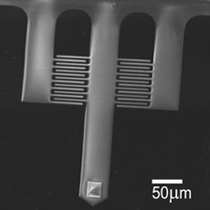
Probes for Imaging and Force MeasurementsImages are acquired using the probe geometry shown in Figure 4 at right. The central long cantilever has an integrated pyramidal tip (similarly to standard SiNX probes from commercial makers), and this tip is the only part that contacts the substrate. The short side cantilevers are treated as being completely rigid, providing a fixed reference point relative to which the beam's deflection is measured. These levers are made in three sizes:
|
Figure 6: Scanning electron micrograph (SEM) and schematic drawing of a typical cantilever demonstrating the probe geometry used for imaging and force measurements. |
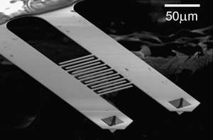
Probes for Thermomechanical Noise MeasurementsThese cantilevers are fabricated as matched pairs, in order to have as nearly identical as possible thermal noise characteristics. Though also made with integrated tips, they are typically not used for imaging. These cantilevers are available in two sizes:
|
Figure 6: Scanning electron micrograph (SEM) and schematic drawing of a typical cantilever pair showing the geometry used for thermomechanical noise measurements (and the Boltzmann's constant experiment). |


Fabrication Process