Design a printer that can be built at a cost on the order of $10 (US$). The target market is poor developing regions of the world.
Do you remember, as a child playing with a magnifying glass in the sunlight? You could burn patterns in a dried leaf, or perhaps an ant or two?
My idea was to make an electronical device which can focus the sunlight and use it to burn a pattern onto a surface. The positioning of the light beam is controlled electronically by a microcontroller, so it can be interfaced to a computer as a low-resolution simple printer or it can use an embedded radio receiver to receive print files via the radio waves. (you can tune in to your favorite book, for example) The printing surface can be anything which burns/browns easily (dried leaf, large piece of bread, etc). I have also found a source of photochromic UV-activated dye, so that you can coat a sheet of paper and just use that as a cheap reusable printing material. (the dye turns dark when exposed to strong UV light, but then gradually fades over time - .5 hours or so) Since the a source of electrical power is also a concern, I think it is possible to incorporate a hand-cranked generator and capacitors to store enough energy to print a single page. Also, it is conceivable that a wind-up mechanical spring can be used to power the moving parts, this leaving the remainder of the electricity needs to just the radio receiver and microcontroller which consume only a few milliwatts at most, and can easily be sustained by solar power or small generator.
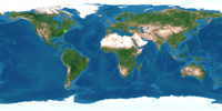
If you don't count the polar regions, the density of information technology is roughly inversely proportional to the lattitude (take a look at a map and see for yourself). The regions of the earth most in need of cheap information technology are central Africa and South East Asia, which happen to be low-lattitude regions with strong sunlight year-round.

My original design was a magnifying glass which focuses the light. I thought of 4 ways in which the beam of light could be steered: 1) actuated mirror 2) actuated prism 3)R-Theta lens (I asked optics guys about this) 4) holographic element
I abandoned this design because the beam steering mechanism was too complicated for large scanning areas. A holographic element (basically a disk) which is moved by a stepper motor would have been great, but this would have required a custom-made element and also I'm not sure if it would have worked with filtered sunlight (since the operation of such interference devices is based on monochromatic laser light) Also, the unit would have required a cumbersome structure to ensure that the main lens was always pointed at the sun.

If the printing area does not need to be large, then an actuated mirror can be used which does not need to rotate over very large angles. An idea I had was to put the mirror on a 2-axis gimbal (similar to a gyroscope) where each axis would be actuated by a magnetic coil. If a 2-channel radio received is used, then the left and right audio channels can each drive the respective x- and y- axis of the mirror actuation. Another advantage of a small actuated mirror is that it can be actuated relatively quickly. The voice coil in radio speakers can then be used both for sound output, but can also be employed to drive the actuated mirror for this solar printer. Actuating mirrors can also be done using MEMS technology.

Instead of steering the beam, I thought it would be simpler if the lens itself moved laterally. It would be fun to build a radio controlled car which would burn a path as it moved around. The car would have 2 main wheels which are powered and also 2 perpendicular "training wheels" to keep it balanced.
Although it would be fun to watch, I abandoned this design because moving a car around is a slow printing process and also registration is a problem, since it would be difficult to accurately control the car's position since the wheels could potnetially slide and slip.

I then thought about an X-Y plotter or X-Y stage, but it did not seem appealing due to it's cumbersome size. The design that I settled on is
what I call an "R-Theta stage." This is essentially a 1-D positioning device, but it can be made to swing about a pivot point to sweep out an area.
The form factor of this device is essentially a bar, so it is easy to carry. The focusing lens moves along the length of the bar using a belt-like mechanism.
The belt is not opaque but is actually a chain-link structure. The pivot end of the "printing bar" can be anchored to the ground using a stake or using
a suction cup and hinge. One stepper motor powers the "belt" which positions the lens along the length of the bar, and the other stepper
motor powers the wheel on the free end of the bar, which controls the angular sweep of the "print head." I think this design is simple, compact, easy to use, and
would have good performance.
If strong sunlight is not available or if the user prefers to just make a quick temporary print-out, then the print material to use is paper coated with photochromic dye. I acquired a sample of this dye and dipped a strip of plain paper in it and let it dry. In the photos below you can see the change when exposed to UV light.
 Coated strip of paper before UV
 Coated strip of paper AFTER brief UV exposure
A low-cost printer is a much needed device to archive, disseminate, and share information. For most needed information (such as drawing maps, plans, or text), high-resolution is not needed. I think this design is a reasonable and practical approach to this problem apropriate for very austere regions of the globe.
Rich Fletcher
e-mail: fletcher@media.mit.edu