|
|
||||||||||||
|
|
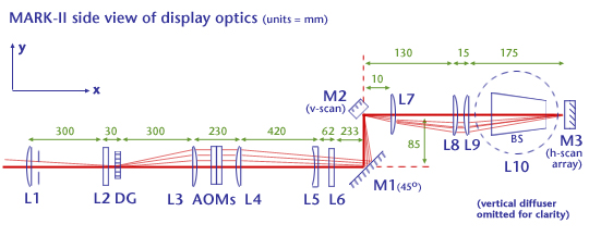
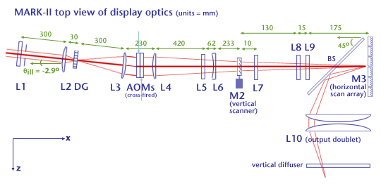
Simplified
sketches of the mark-II optical paths and beam-shaping optics are
represented below, along the horizontal and vertical axes. A brief
description of the system's architecture follows. |
|||||||||||
| |
||||||||||||
|
|
 |
|||||||||||
|
||||||||||||
|
HORIZONTAL AXIS: The horizontal axis beam shaping optics consist of a simple beam expander composed of lenses L2 and L3. The telescope formed by those lenses magnifies the 2mm diameter input laser beam by a factor of 7.5. The central portion of the collimated expanded beam illuminates the two acousto-optic modulators. These are placed back to back, with their surfaces almost touching each other. Their orientation with respect to the laser (about 2.9 degrees for 633nm illumination) is chosen to satisfy the Bragg condition at the center frequency and is then fine-tuned to get the flattest possible response across the passband (50-100MHz). The two lenses L4 (f4=600mm) and L6 (f6=-150mm) are used in a telescope combination, in order to shrink the physical footprint of the display. The output imaging lens L10 (320mm diameter; 250mm F.L.) was chosen to provide a 30-degree field of view for a 50MHz analog bandwidth signal sent to the AOMs. HORIZONTAL SCANNING OF THE FOURIER PLANE: Design of the horizontal scanning assembly involves the use of a set of tiled galvanometric scanners, mounted in a configuration designed to minimize the width (and inertia) of each mirror and shrink the gaps between them. The mark-II currently uses 3mm thick, 6mm high, and 20mm-wide fused silica mirrors mounted on galvanometer bodies (model 6350 from Cambridge Technology (Watertown, MA)). Galvanometer bodies are mounted on a thick aluminum plate which also serves as a heat sink. These mirrors are carefully physically mounted and painstakingly registered by adjusting the individual servo response of each galvanometer. Triangular waveforms are used to drive the scanners,with both scan directions serving as active write intervals (one for each cross-fired AOM). The active scan time per horizontal line is determined by the cheops firmware to be 2.4ms. There are two active intervals per scan period; the scan frequency is set ot 150Hz which permits a 0.9ms inactive period between each active interval. Each mirror's total mechanical excursion in each scan direction (including during inactive intervals) is 18 degrees. Within an active interval, during the time each mirror rotates at a constant velocity of 109rad/s, a 30 degree optical range is deflected. A total frame includes 4 complete (forward and reverse) active horizontal scan periods; an inactive period is added after each frame as a vertical retrace interval. The overall display refresh rate is (150Hz)/(4+1) = 30 Hz. VERTICAL AXIS: Because the fill ratio of the AOM's acoustic channel is about one third, it would be inefficient to illuminate the crystal aperture by just vertically expanding the incoming beam. Thus, an optical system was designed to properly shape the beam introduced into each acoustic column. The key element in this design is a Damman grating, manufactured by the National Institute of Optics (Quebec, Canada) which separates the incoming beam into 19 orders of equal power. The angular separation between orders is equal to 50 milliradians. This Damman grating is placed in the confocal plane of lenses L1 and L3. Choosing the focal length of L3 equal to 300 mm results in a vertical stack of light sheets spaced 4mm apart; this spacing corresponds to the AOM's interchannel spacing. The thickness of each sheet is determined by the width of the incoming beam multiplied by the magnification of the L1-L3 telescope. In this system, f1=f3=300mm for a unity magnification factor, since the raw laser beam is just about equal to the acoustic width. The height of the AOMs are adjusted so that the light sheets and the acoustic columns are vertically registered. Lenses L4 and L5 focus the light diffracted by the AOM onto the surface of the vertical scanning mirror M2, after a vertical relay by M1. Compared to the horizontal scanning assembly, the vertical scanning section of the system is simple (the mark-II exhibits no vertical parallax). Basically, the vertical scanning is effected in a raster fashion (30Hz, non-interlaced, sawtooth-driven) and the retrace interval is equivalent to a full horizontal scan interval (6.66ms). Because the system's vertical focal plane is fixed and horizontal focus is variable, deep images exhibit some astigmatism, just as they do in any horizontal-parallax-only display. VERTICAL SCANNING: The geometry of the vertical scanning subsystem results in a very narrow viewing zone and requires placement of a one-dimensional (vertical) diffuser in the vertical focus plane. This diffuser spreads each hologram line in the vertical direction but leaves horizontal image content unaffected. The system currently uses a one dimensional holographic diffuser manufactured by Physical Optics Corp (Torrance, CA). It produces a total angle of diffusion is 30 degrees in the vertical direction and very low scatter along the horiontal axis. A cylindrical doublet L7 is placed immediately after the vertical scanning mirror, and determines the vertical focal plane of the scanned array in the image plane. The cylindrical doublet L8 and L9 images the vertical scanning mirror on the horizontal scanning plane. The output doublet L10 then images the AOM array in the center of the image plane. The vertical transverse magnification is essentially determined by lenses L4, L5 and L10. For an image plane aspect ratio of 2:1, (where the image plane measures 150mm across and where the 75mm vertical extent of the image plane is determined by a stack of 8 sweeps --4 forward and 4 reverse-- of the AOM's image) the required magnification is 75mm / (8*67mm) = 0.14. *Note:
This description of the mark-II has been adapted from: Pierre St.-Hilaire,
Scalable
Optical Architectures for Electronic Holography, Ph. D. Thesis,
Program in Media Arts and Sciences, Massachusetts Institute of Technology,
September 1994, where more thorough documentation of the display
architecture can be found.
|