The Power System
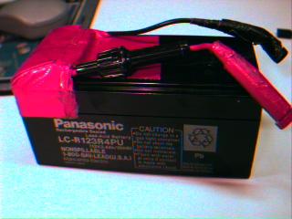
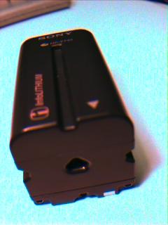
Batteries
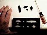
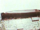
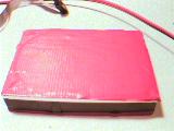
Power Converter (images show Datel)
- The Datel UWR-5/3000-D5 converter converts 4.5 to 13.2V DC into
the 5V DC the PC/104 boards expect. See the specs that come
with it for exact information.
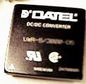
Note again, a higher voltage version might be preferrable,
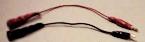
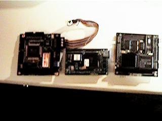
- Find the PC/104 power connector from the Ampro kit.
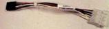
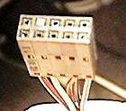
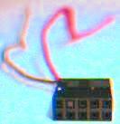
Allign the PC/104 power connector as shown below. Note that the
connector is "keyed" (i.e. one pin hole is blocked so that it
can be attached only one way).
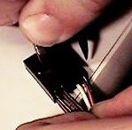
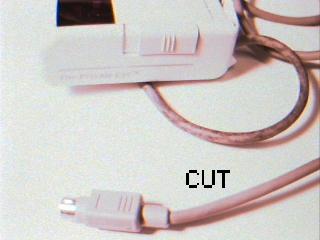
Remove all the leads
except for the two leftmost (red and black: positive and
negative). The leads can be removed from the small connector by
simply pressing on the indicated spot and pulling.
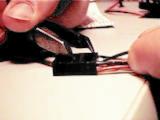
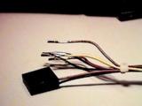
Cut off the large connector, and strip the extraneous wires so
that it looks like this:
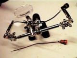
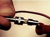
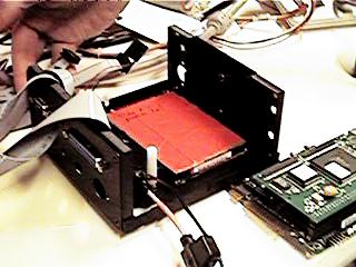
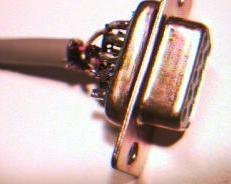
- Attach the PC/104 power connector to the output side of the DC
to DC converter. Note: to make the most stable connection,
wrap the wire around the pin of the converter, bend down
the pin of the converter, and solder in place.
IMAGE
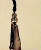
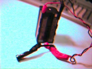
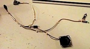
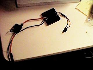
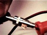
- Attach a fuse holder to the positive pin on the input side of
the DC converter. Insert fuse (about 10A).
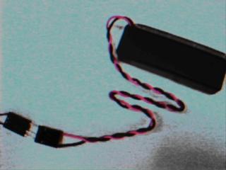
- Attach about 3 feet of stranded wire (preferably red and black
18 gauge) to the input side of the DC to DC converter. Note
that the fuse holder replaces a section of the (positive) red
wire. The result should look like
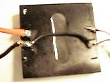
- If you wish NOT to have an isolated converter, connect the
negative pins to each other as shown here. Isolated converters
are convenient for those doing medical experiments (due to
regulations) or those who plan to plug their wearable into
something besides batteries.
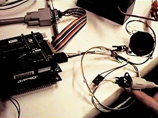
- Attach male banana jacks (red and black) to the end of the
wires. Here's how to use the Radio Shack jacks we use
- Test the converter by plugging it into a battery and testing
the output (should be 5V DC).
- Place a layer of cardboard on top of the connections for
insulation, and use (preferably black) duct tape to hold it in
place. Keep the front of the converter clear since it will get
hot. Insulate any remaining exposed wire with the tape.
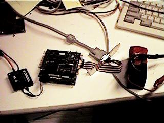
Making the computer
Installing Software
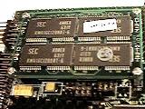
Install the hard disk using the small IDE cable provided in the
kit. One end of the cable
goes to the CPU board, the other to the
hard drive. The cable is keyed, and the position of the connector on
the cable does not matter. Power to the drive is provided through the
cable.
The next step really depends on what you want to do, which OS you
intend to run, and what you have available. I suggest starting the
case instructions while waiting for software to install.
MEDIA LAB FOLKS SKIP THE NEXT DISCUSSION
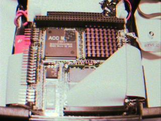
For most folks, attaching hard and floppy drives as in
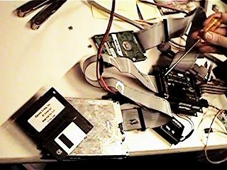
and going through a floppy install of the OS is the easiest way to
install software. Note that the hard drive installs on the back of
the CPU board and the floppy on the left side (where the screwdriver
points). Other methods include buying a IDE CD-ROM and installing it
on the second connection on the IDE cable. To do this, a small to big
IDE cable adapter kit is necessary. Toshiba
makes something called the HD002KU2.5 - Install kit for 2.5" HDD
which should do the trick, and a standard PC power supply is needed to
provide external power to the CD-ROM (can be picked up at any computer
store). Yet another option is to plug the wearable into the net with a
Dlink, boot Linux from a floppy, and download the OS from the net.
Other options include downloading the OS over a serial port, hooking
up the 2.5 inch drive into another machine, or programming the OS into
flash (optional on the Ampro boards).
At the lab we use (and highly recommend) Linux (we are currently
using the 2.0.21 kernal). A good beginning book on the subject is
Using Linux published by Que. Shows how to install the
software and perform many configurations.
We provide drivers for X for the Private Eye, Twiddler keyboard,
and Sierra Wireless modems on the main pages. Most everything else is
probably already written with source provided on web sites or in
standard Linux distributions (Slackware, Red Hat, Debian, etc.). In my
personal experience, Linux, even though public domain, tends to
provide better supported than what Microsoft can provide - its just a
matter of knowing where to look. In the worst case, it's usually easy
to write new device drivers in Linux.
For those who insist on Microsoft Windows, I believe drivers
exist for most
of the equipment we use. However, they tend to be less flexible and
robust. If using DOS, be aware that battery life
may be halved compared to Linux. This rather fantastic result is
supported by precise testing. The current theory is that the
powersaving 486/586's used in the CPU boards execute low-power "hlt"
instructions in Linux's idle loop while DOS is doing something else.
Have not compared to Windows.
FOR MEDIA LAB FOLKS
And folks who have a friend with a disk with
software already installed (assumes linux and that the same model
hard disks are being used), the following procedure will make a
copy of the disk.
- Let's call the hard disk with software installed the
"master" and the one without data the "slave."
- Jumper the slave to be the second (slave) hard drive. For
the Toshiba 2.5" drives this is as shown:
- Plug both the master and the slave disks into the IDE
cable. Make sure the circuit board on the drives can not
short into anything.
- Boot Linux.
- Type "dd if=/dev/hda of=/dev/hdb bs=18k"
- After a long while, the copy will finish.
- Take both drives off, unjumper the slave, reattach the
slave, and make sure it boots.
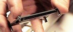
Preparing the case
- Unscrew the case screws about 1 turn. The case should slide
apart easily.
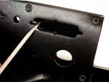
- Place the edge of the case on a desk. Use a screwdriver to
work the punchouts on the IO panel back and forth until they
come out.
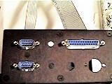
- Attach the serial and parallel ports to the case (use the hex
nuts so that devices can be secured to the ports).
Putting it together.
IMPORTANT: Follow the instuctions below to lay out the components once before
doing it for real. This will forestall surprises.
- Place 2 stacks of 2 standoffs in the standoff holes in the
case. Use plastic standoffs where possible
- Place the DC to DC converter on the bottom of the case trying to
keep the non-taped surface of the converter against the case (for heat
dissipation).
- Place approximately 1/2" of insulating material (for example, the
packing material from the VGA board works nicely) next to the
DC converter.
- Temporarily undo the male banana jacks from the DC converter to
run the power wires out of the medium-small round hole in the front of
the case.
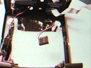
- Attach the clock battery to the utility connector. Duct tape
the connector to make sure it stays.
- Attach the keyboard port to the front of the case. Place the
"on" LED in one of the smallest round holes on the front of the
case.
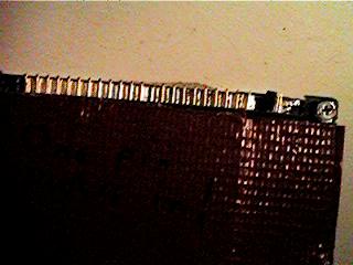
- Cover the pins on the bottom of the CPU board in duct
tape.
Bare pins
Covered pins
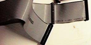
- Cover the bottom and top of the disk drive (BUT NOT THE SIDES)
in duct tape to insulate it.
- Plug the IDE cable into the CPU board, and put a right angle
bend in it.
Hook up the other end to the hard drive, and
wrap the cable around the hard drive so that it will fit under
the CPU board.
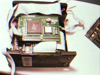
- Place the CPU and disk in the case, and screw in a third layer
of standoffs to hold it in place.
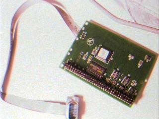
- Attach a standoff to the hole furtherest from the front of the
Private Eye driver board. Attach the driver board to the CPU
module.
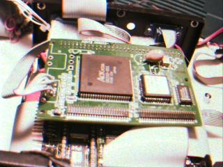
(Note that in this image the Private Eye driver board 8 pin
connector has already been replaced)
- Attach the serial, parallel, Private Eye, Keyboard, ports to
the boards.
- Plug the Private Eye into its driver board, and test the system
to make sure the machine boots.
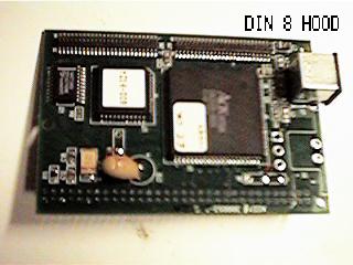
Private Eye modification
If you've completed the above instructions, the Private eye 8 pin
connector sticks out of the right hand side of the case too much.
There are several ways to handle this
- Cut a hole in the case to accomodate this connector
(a dremel tool with cutting disk is useful for this).
- Buy a male to female straight through DIN 8 extender and
attach the result to the front of the case
- Attach a new connector using the instructions below.
In general, we find the DIN 8's to be too unreliable (get bumped
out). So, instead, we replace the connector on the board with a cable
to a DB9 male connector that can take the place of the first serial port
on the front of the case. The first port is then simply hung off the
back of the machine. The Private Eye cable itself is then replaced
with a female DB9 which can be screwed into the matching connector in
the case. SO:
- Desolder the present 8 pin connector.
This takes a combination
of patience and ruthlessness. The main trick is not to heat up
the solder joints more than necessary to remove a pin and not
to slip accidentally, cutting traces on the board. First remove the
DIN 8 connector's hood.
A soldering iron and a pair of
needle nose pliers can be used to push and pull the soldered
tabs out (there are no connections to worried about). Once
the hood is off
the DIN-8 pins can be desoldered. The easiest (and pretty
ruthless) way is to cut slowly through the plastic of the
connector, cut one of the pins, grab it with needlenose pliers,
and heat up the solder joint until it comes out.
- The solder holes can be cleaned of residual solder by using a
solder sucker.
While this helps ease the next steps, it is not necessary.
- Take a serial cable with a DB9 male connector on it; cut off
the other, square end; separate, strip, and tin
the ends of the wires.
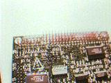
- Solder the leads into the driver board according to the
following table. Wire number 1 on most serial cables is a
different color than the rest (e.g. red). Looking at the bottom of the
Private Eye
driver board (the side WITHOUT the large chip), the holes are
numbered
   ---------+
      1234  |
      5678  |
            |
These tables are for our convenience; any one
to one mapping will work. The mappings are for backwards
compatibility with previous iterations of the driver board.
Private Eye driver board	DB9 cable
-----------------------------------------
1		                5
2	                        2
3	                        1
4		                3
5		                8
6		                7
7		                6
8		                4
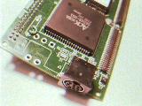
The result should look like (from the bottom of the Private Eye
driver board):
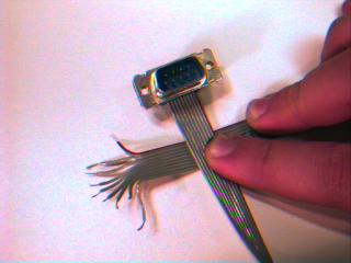
- Cut the 8 pin connector off the end of the Private Eye.
- Rewire, using the following table, the Private Eye to a DB9
female connector.
Private Eye connector	female DB9 (as labeled on the connector itself)
----------------------------------------------------------------------
yellow(1)		1
blue  (2)		6
green (3)		2
white (4)		7
brown (5)		3
red   (6)		8
black (7)		4
orange(8)      		9
Altogether, you should have something like
- Test the system to make sure the wire is correct.
- Strain relieve and properly case the connector: Partially
assemble the strain guard

and place it on the cable. Determine where it should be placed
such that strain will be put on it and not on the DB9 solder
joints.
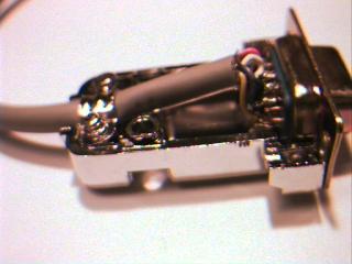
Finish assembling the strain guard and tighten in place. Note
that for the thickness of the Private Eye cord, the plates of
the guard have to be nested together like spoons in order to get a tight
fit. The result should be tight enough that it should be almost
impossible to slide the strain guard along the cord.

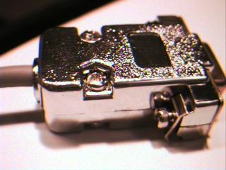
Place the assembly into the DB9 case, slide the 2 fastening screws
into place, and put the 2 RS232 captive screws in their positions
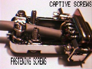
Close the DB9 case.
The captive screws enable fastening the Private Eye connector to
the case.
Finishing up
Congratulations, you should now have a robust wearable computer. The
next stage is making it comfortable to wear. The next section,
"Customizing," describes at least one way of doing things but may also
list alternatives. Please read all alternatives before trying
one. The reader is encouraged to try their own solutions.
Copyright 1997, Thad Starner and MIT
Warrantee (or lack thereof)
Last modified: Sun Mar 16 21:17:47 EST 1997