How to modify a Locust board for RF
A. Loffler (
Alex.Loffler@bt-sys.bt.co.uk)The Locust board was designed as a solution to in-building location awareness for wearable computing devices. For more information on the Locust as a location beacon, please see the Locust Homepage.
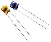
The original Locust (an IRX2.0 board) had bi-directional IR (Infrared) capability. Although IR is a useful communications medium, it has the disadvantage of requiring line-of-sight which proved extremely limiting for a wearable device. A much more desirable alternative would be RF (Radio Frequency) as it does not require line of sight and with the recent introduction of devices such as the MPT 1340 (Figure 1a), low power, low cost RF is attainable. The MPT 1340 is a 418MHz AM Transmitter capable of transmitting at 1200bps with a range of up to 100 meters. It’s opposite number the Super RX (Figure 1b) is an AM receiver. Low Power Radio Solutions (LPRS) produce both devices.
Figure 1a - The MPT 1340 a 418MHz AM Transmitter
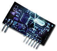
Figure 1b – The Super RX AM Receiver
The following information will outline the steps needed to convert a Locust (IRX2.0) board into either a RF receiver (worn as part of the wearable) or a RF transmitter (a Locust beacon). The modifications make use of unused IO pins and as such do not affect the current capabilities of the IRX board.
The Transmitter
These must be as low cost as possible (as we require many location tags), have a fairly low range (typically 3-5 meters) and each should emit a unique ID (in order that the wearable can determine its location). The data sheet for the MPT 1340 transmitter are included for completeness (PDF format).
Step 1 – Modifying the board
The original Locust is shown in Figure 2. In particular note the prototype area to the left of the PIC Processor.
Figure 2 – The original Locust
We will be using the I/O port RA2 that is located on the row just under the resistor R2. All descriptions will relate to the board as oriented in the figure above. E.g. the top of the board is the long side furthest away from us and the left edge has all of the IR devices.
The first step is to make the connection between the I/O section and the prototype area on the board. On the above board, it would mean making the jumper connection on the third set of pins. Most boards do not have jumper pins, so just solder across the holes.
We then need to put a 220pF capacitor between RA2 and V+ (parallel to R1 & R2).
Once this is in place, put the transmitter next to the capacitor, again parallel with the resistors, between RA3 and V+. Make sure polarity is observed (black mark towards V+).
Turn the board over and make a solder link between the capacitor and the transmitter. (On the I/O side of the devices!)
To complete the modification, measure out a 16cm length of wire (to be used as the antenna). This should be soldered to the left-hand hole of the I/O pair for RA3.
Step 2 – Blowing the PIC
The Transmitter PIC Code is fairly simple. It was written such that it is as efficient as possible with regard to power consumption. The code simply transmits a six byte (unique) ID every 300-500ms. Between transmissions, the PIC is put into sleep mode where it draws very little current.
The C source can be found here. It should be compiled and blown to a 16C84 PIC.
The Receiver
The receiver should be robust and should also be as sensitive as possible in order to reduce the required signal strength from the transmitter. The receiver listens for a signal. If one is found it grabs the data, validates it by comparing checksums. If the data passes, it is output in RS232 format for the host. We have used two different receivers, the Super RX from LPRS and the CR75S from Maplin. Pick one of the two sets of instructions, below:
Step 3 (alternative 1) – Modifying the board: Super RX
The RF receiver comes as an 8-pin device. We are only interested in three of these pins.
It was found that the crystal used to clock the PIC interferes with the performance of the receiver. To minimize this we placed a piece of ribbon cable between the Locust board and the receiver.
We will be using RA2 again. First complete the jumper link in the I/O section of the board (either by fitting a jumper or making a solder link).
Find a 3-wire ribbon cable that is at least 10cm long. That's enough to get it away from the interference from the PIC, though if you want to have the PIC near your main CPU you might want a longer cable for convenience. One end of the ribbon cable should be connected to the Locust as follows:
The other end of the ribbon cable should be connected to the receiver as follows: (The pin-outs for the receiver are shown in Figure 3.)
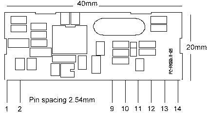
Figure 3 – Pin-outs for the Super RX
Finally, measure out a 16cm length of wire (to be used as the antenna). This should be soldered to pin 2 on the receiver. Any unused pins may be trimmed as appropriate.
Step 3 (alternative 2) – Modifying the board: CR75S
The CR75S receiver is a 10-pin device, and unfortunately we have to hook up 6 of them. As with the Super RX, we'll use a ribbon cable between the IRX board and the receiver.
We will be using RA2 again. First complete the jumper link in the I/O section of the board (either by fitting a jumper or making a solder link).
Find a 6-wire ribbon cable that is about 10cm long. Next one end of the ribbon cable should be connected to the Locust as follows:
The other end of the ribbon cable should be connected to the receiver as follows: (The pin-outs for the receiver are shown in Figure 3.)
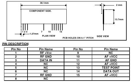
Figure 3 – Pin-outs for the CR75S
Finally, measure out a 16cm length of wire (to be used as the antenna). This should be soldered to pin 3 on the receiver. Any unused pins may be trimmed as appropriate.
Step 4 – Blowing the PIC
The last step is to blow the receiver code to a PIC for the receiver board. The code continuously listens for a preamble. Once found it stores the incoming data and validates its checksums. If the data passes, the LED on the locust is blinked and the data is sent to the host via its RS232 port. The code can be found here.
Further Extensions
A problem with the transmitters is that the unique ID is hard coded into the PIC. At the time of writing we have some code that allows modification of the transmitter ID via IR. This code is still a little unstable but it will be released as soon as the bugs are ironed out.
Any problems/suggestions are welcome, and should be sent to the address at the top of this page.