Sample Positioning and Motion Control
The educational AFM uses a fixed cantilever (held without moving), and actuates the sample stage to accomplish imaging and force spectroscopy.
For vertical (z-axis) movements of the stage, there are three regimes of motion:
- Manual(coarse): turning the knob on the red picomotor by hand.
- Stepper motor (medium): using the joystick to drive the picomotor (pushing the joystick forward moves the stage upward).
- Piezo-disk (fine):actuating the piezo disk over several hundred nanometers using the MATLAB software.
Coarse Positioning
3-axis Stage
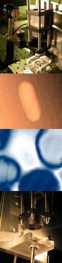
The stage used is a Newport 562-XYZ, equipped with two SM-13 micrometers, which are used for coarse positioning along the x- and y-axis. These are ised for sample-plane motion both before engaging the tip, as well as during imaging. The z-axis actuator is a New Focus stepper motor (see below).
Medium Positioning
Stepper Motor
To achieve fine-resolution long-travel actuation needed to engage the AFM tip, a New Focus Picomotor™ system is used. The 8301 motor provides 1/2" of travel with ~30nm step size resolution. The motor can be driven by hand or with a joystick. The full New Focus system requires an Ethernet Controller (8752), a Driver (8753), a Joystick (8754) and Power Supply (8755), as well as cables to interconnect them.
Fine Positioning
The Piezo Disk Scanner
|
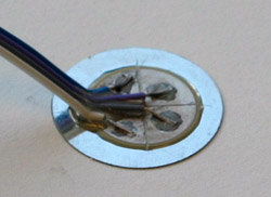
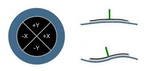
For scanning and force spectroscopy measurements the sample is actuated by a simple piezo disk actuator, shown in the figure to the right. This is designed after John D. Alexander's "Simple STM Project," which includes an explanation of the operating principles of the disk scanner, as well as how to make one using part number P9924-ND (EFB-RD24C411) from DigiKey. The disk is divided into quadrants and flexes to move the post on which the sample stage rests.
Once the disk has been properly prepared, and the leads connected, it's clamped in a custom-machined holder, and mounted to the X-Y-Z support stage. Magnetic sample pucks (Veeco part: SD-101 or SD-102) are placed on top of a steel offset post, held to the steel piezo actuator backplate using a small permanent magnet. An offset post of 1.5" length allows the sample to be moved over an approx. 15µm square area in the x-y plane. Shorter offset posts will limit the travel range, but enhance stability. |
Figure 3: The piezo disk actuator subdivided into quadrants, showing the z-axis actuation mode at the upper right, and x-y-plane actuation mode on the lower right. |
Piezo Drive Electronics
In addition to its low cost, another key advantage of the piezo disk actuator is that only moderate voltages (±40-50V) are required to achieve a sufficiently large scan range for useful imaging. With a 1.5" long offset post, drive signals of ±40V give a scan range of approx. 16um square.
The waveforms driving the piezo disk are generated by MATLAB scanning software. Since the PC DAQ output hardware is limited to a range of ±10V, a simple op-amp circuit provides 4x amplification to ±40V, using OPA445AP high-voltage op-amps (datasheet). The amplifier board is powered using a dual-DC power supply from Acopian (±45V -- part #45GT10D-45GT10D). The schematic of a half-circuit (driving one of either the X or Y channels) is shown below.
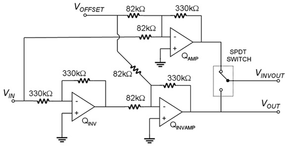
An optional VOFFSET signal can be input to the circuit to apply a common offset voltage to all four piezo quadrants simultaneously, enabling the user to make fine adjustments to the z-axis bias point.
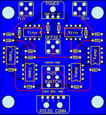
Circuit design and layout files are available for ProTel (download .ddb and .ldb) -- please contact us by e-mail if you prefer alternative formats - limited other may also be available. PCB design files (suitable for use with a custom PCB vendor such as Advanced Circuits): . For a complete listing of parts, download the parts list. [Note: ProTel design software seems to have been superseded by Altium Designer.]
|
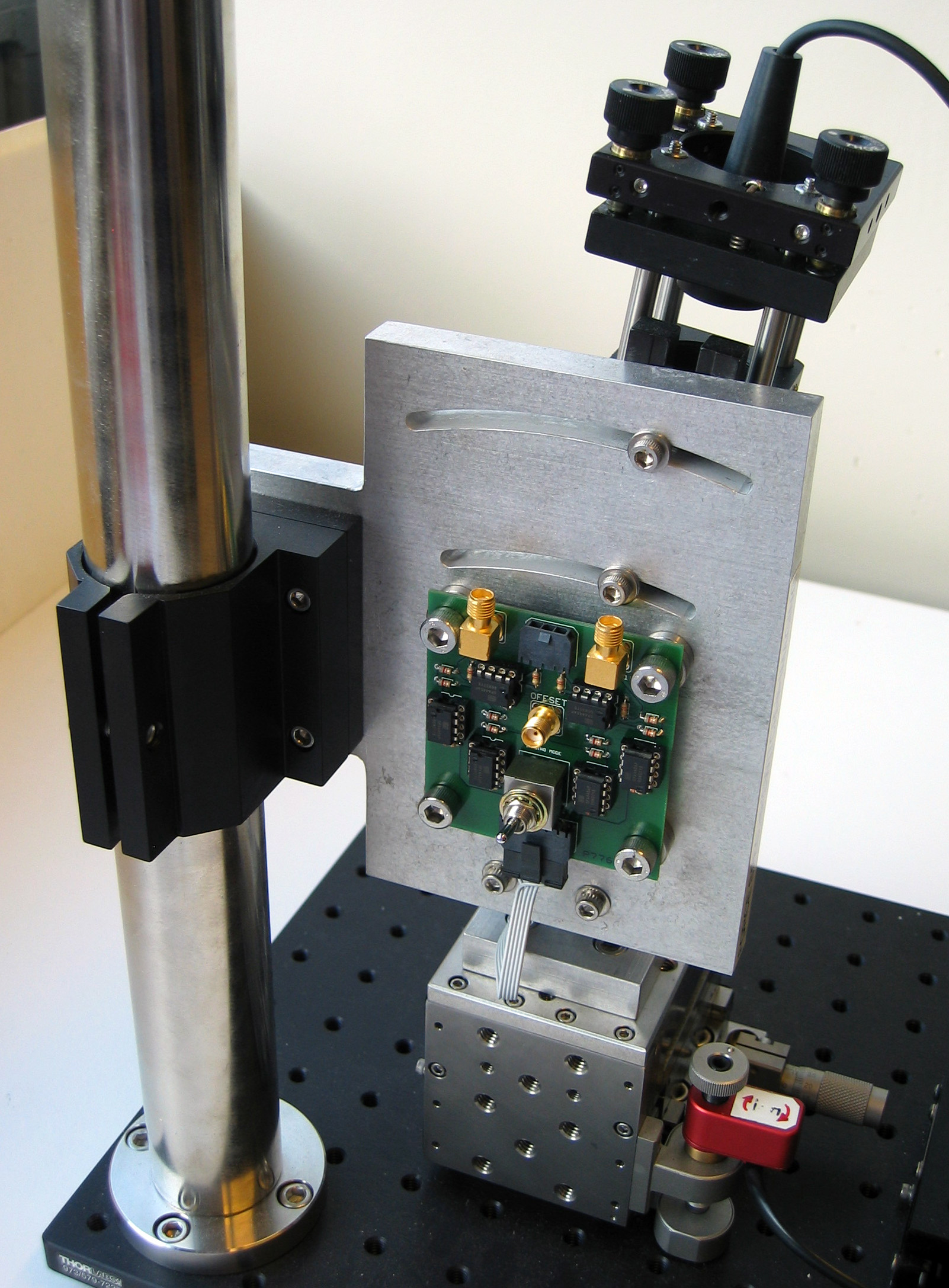
Figure 5: Layout schematic (left) and photo (right) of the electronics board used to drive the piezo actuator. The board measures 2.6" x 2.4". In the image at right, the connector at the bottom is the ribbon cable that attaches to the piezo disk (see also the rear photo the AFM). |

For more details about the modes of actuating the piezo disk, and the relationships between the signals involved go here.