Optical Components and System Layout
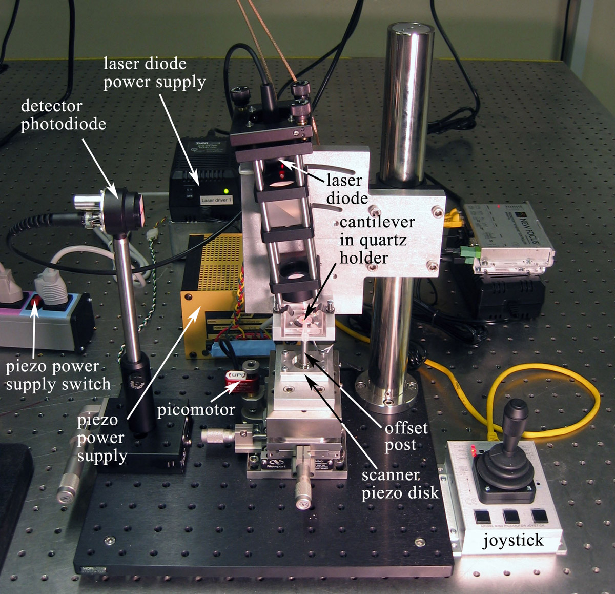
This system is built almost entirely from off-the-shelf components (non-standard parts are described below), and can be assembled in approximately a day. This page describes the overall layout and optical system. The whole-system photo is the best reference for assembling the AFM.
Optical Core
Laser Source
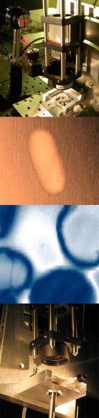
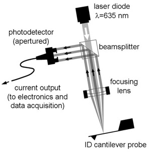
The probe's ID fingers are illuminated by a coherent light source (laser), which is collimated (ThorLabs LT230P-B but with a C110TME-B lens, using AD15F to mount inside the SM1 cage plate), then focused down (ThorLabs AC254-040-A1) onto the diffraction grating (spot size 10-20um), and the diffractive modes are steered by the beamsplitter (ThorLabs BS013) onto the photodetector as they reflect upward. The collimation/focusing optics and beamsplitter are rigidly mounted using the cage plate system to the single-piece AFM head, and to which the cantilever probe holder (Veeco FC) is also rigidly attached.
The laser source is a 5mW laser diode with a wavelength of 635nm. Our setups use a ThorLabs HL6312G, but any laser diode with similar specs should work. The diode is operated in constant-power mode, driven by a ThorLabs EK1011 driver kit (the kit should have its DIP switches set properly to match the monitoring current Imon of the laser diode of choice. For the HL6312G, the switch configuration is 00010). The driver is typically adjusted to give an output laser power of approx. 1mW, as measured after the beamsplitter (~2mW initial output), making this a safe Class II laser device.
For more details about the ID cantilevers, see this page or Section II in the AJP paper.
|
Optics Building ConsiderationsA few key recommendations to help ensure that the optics function as intended.
|
Figure 2: Schematic showing the layout of the main components required for the AFM detection optics. |
Photodetector and Readout Electronics
Our detector of choice is the DET110 from ThorLabs (PDF datasheet here: [Note, April 2007: this has been discontinued, and the most similar part currently available is the DET36A]). A 100kOhm resistor to ground converts its current output to voltage, providing a signal of approx. 1V peak-to-peak to the amplifier, oscilloscope, or data acquisition board.
Because the ID cantilever mostly rejects mechanical vibrations and disturbances that do not come from the out-of-plane displacement of the cantilever probe itself, the detector can be mounted separately, with minimally stringent rigidity requirements. Our detector is moved using a Newport 423 single-axis long-travel stage, actuated by an SM-25 micrometer. A set-screw adjusted sliding rail mount should be an acceptable lower-cost alternative.
Custom-machined parts
Several parts for mounting AFM components are not available off-the-shelf. These are simple to specify and can be requested from any machine shop for approx. $400-500 per set. PDF files of the parts drawings are provided below, as well as SolidWorks part and drawing files.
- Head Plate (SLDPRT, SLDDRW)
- Stage Mount (SLDPRT, SLDDRW)
- Piezo Clamp top (SLDPRT, SLDDRW)
- Piezo Clamp bottom (SLDPRT, SLDDRW)
- Fluid Cell Mount/holder (SLDPRT, SLDDRW)